Combination locks are often encountered. They hang on gym bag straps, secure garden sheds or guard the doors of storage units. They are everywhere. But few people stop to think about the complex design that humming quietly inside the plastic and metal cases. How can a simple dial or keypad translate your input into physical security?
Unlocking the secrets of a combination lock requires more than brute force. You need to understand the precise mechanical interactions between springs, levers and cams. If the internal mechanisms are easily accessible or easily bypassed, the lock will not be able to prevent unauthorized access, which is its purpose.
Finally, when you remove the case, you won’t find any wires or circuits. Instead, you’re greeted by a compact assembly of mechanical components. It is an incredibly dense collection of parts, each with a specific role in maintaining the integrity of the lock.
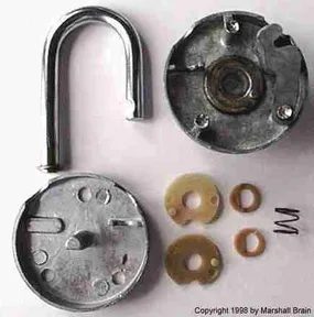
If you look inside, you will find the following items:
- The Dial or Keypad Interface : Code entry point.
- The Cam : The rotating part that attaches and detaches the shackle.
- Tumbler Wheels or Discs : A key logical element that must be perfectly aligned.
- Springs : Provides tension to hold parts in place or to snap them back into place.
- Shackle : A U-shaped rod that is locks through the hasp or loop.
All parts work together. A single misalignment, it means the lock stays closed. This is no accident; it’s a system built for precision.
Standard combination locks rely on a tight mechanical dance inside the case. It’s not just the dial that turns the yoke. It’s about alignment.
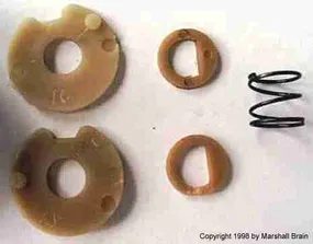
There are usually three cams inside. These are the rotating parts that engage and disengage the locking mechanism. But they are not all equal.
One cam is metal. Glued directly to the rotating surface of the lock. This is the part you turn. This is the primary interface between fingers and mechanism.
The other two cams are plastic. Do not touch the dial directly. Instead, they hold the components together and ensure that the metal cam rotates at the correct time.
Between these three cams there are two plastic spacers. These little rings are very important. Maintain precise distance Without these, the mechanism will not work. Even worse, it wouldn’t engage at all.
“Gaskets are more than just fillers; they maintain tolerances.”
If you’re repairing a lock, you will often encounter problems here. Plastic cams can wear. Spacers can crack. The metal cam, usually hardened steel, and last longer, but they can still rust.
don’t skip the spacers when changing parts. Although it looks good. They carry most of the friction. A worn spacer changes the alignment. If they are misaligned, it means that the combination will not work.
Do I need tools for the inspection? A small pick or thin screwdriver. You don’t need much. If the lock is open, it is enough to carefully separate the layers.
Safety? The risk here is minimal. No springs flying. No high voltage. However, watch out for small plastic parts. They disappear easily. Keep your workspace clean. If the spacer is missing, the lock cannot be installed correctly.
Why is this important for DIY users? Because most lock failures aren’t about the combination being wrong. They are related to internal wear and tear. Understanding cam and spacer placement will help diagnose if the lock needs lubrication, parts replacement, or just cleaning.
This is mechanical. It’s very simple. But it’s not foolproof.
Which locks use this model? Most padlocks. Some lockers. Older safes. Newer ones can use electronic solenoids. However, the mechanical core is the same.
If you decide to disassemble one of these, note the orientation. Mark which cams are metal. Which is plastic. The spacers might look identical. But their location matters.
A little patience goes a long way.

Securing the Cam Stack
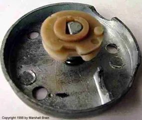
This mechanism is based on a shaft molded directly into the back of the lock body. You drop a stack of cams on this shaft and tension the entire assembly with a spring.
That spring does the heavy lifting. It presses down on the cams, which creates friction between the layers. Without this pressure, parts would just slide apart or rattle loose. Friction holds everything in place and keeps the lock stable until the mechanism needs to be turned.
“The spring creates friction between the cams and holds them in place.”
It’s a simple design. No glue. There are no screws. Pressure and friction work together to keep your hardware secure.
You can see that the shaft is part of the lock body. It’s not an add-on. That is, when assembling the lock, you must make sure that the shaft is clean and free of debris. Dust can reduce this necessary friction. Adding a small amount of light oil makes it easier to move, but too much makes the grip slippery.
As the spring loses tension over time, the cams will wobble. The lock feels loose. You may hear a click before it locks completely. In this case, the spring must be replaced. Or the cams themselves wear out and losing their ability to grip against each other.
Check the tension. If the stack slides off the shaft when you gently shake it, there is a problem. Tighten the spring. Replace the stack. Or both.
This is not a “set it and forget it” component. Regular inspection is required. Especially in doors with heavy traffic. Constant cycling wears down metal. The spring fatigues. Friction is reduced.
Think about the forces involved. Every time you turn the key, you are fighting that spring. You are compressing it further. Over time, this metal lose its springiness. It will not push back as hard. The friction will fade. The lock will fail.
Plan for maintenance. Keep a spare spring handy. Keep the shaft clear. Also watch for that wobble.
When it starts to feel loose, fix it before it breaks completely.

Most people just turn knobs and hope for the best, but there’s a precise mechanical dance going on inside these locks. The cams is at the heart of the process. They are not just spinning discs. They are rotating discs. These are the moving parts that physically handle the locking mechanism.
Tooth shape
Each cam has teeth embedded on both sides. This is not a decorative thing. These teeth are designed to catch and engage as the assembly rotates. Turning the combination forces these cams to work in a specific order. The teeth lock together and the rotational force is transmitted from the dial to the locking bar. If it is done in the wrong order, the teeth can slip or jam, causing the lock to remain closed. The principle is simple, but exact alignment is required.
Indentation system
The real magic happens when you enter the right combination. Each cam has a specific indentation or small grooves carved into its surface. When you dial a number, these grooves will line up. Once the correct combination is achieved, each recess in the cam will line up perfectly in a straight vertical column.
This alignment is the only barrier between you and access.
Releasing the Hasp
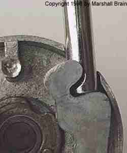
Once the notches are aligned, the latch path is free. The latch that holds the end of the lock firmly in place can now drop into the aligned indentations. It fits snugly and slides into the groove created by the cam. This action disengages the latch from the hasp.
The hasp is no longer held back. The tension is released.
“The latch is able to fit into the indentations and release the hasp.”
Without this precise alignment, the latch cannot drop. The cam teeth prevent it. No matter how much force you apply to the lock, the mechanism stays locked. This is a binary system. Either the grooves line up or they don’t. There is no middle ground.
Why this is important for DIY users
Understanding this interaction is important when repairing padlocks or building custom lockboxes. You don’t need to machine the cam yourself, but you do need to know how they wear out. The teeth can strip. Over time, the indentations may become rounded. When this happens, the lock may feel “sticky” or fail to release even with the correct combination.
Inspect the cams to see if the lock feels stuck. Check for worn teeth or misaligned grooves. Sometimes you just need to a clean with solvent and a drop of oil. In other cases, the internal geometry may be compromised and replacement may be the only option.
The beauty of this design is its simplicity. There are no electronic devices. No batteries. Only metal teeth and grooves work in harmony. But simplicity also means vulnerability. If the alignment is off by a fraction of a degree, the lock will fail. This is why precision manufacturing is so important. Therefore, understanding how the latch interacts with the cam notch can save you time, frustration, and potentially your belongings.
What happens if the latch falls? The hasp swings free. The lock opens. However, it is only when it closes again that the mechanism resets and the teeth re-engage to await the next combination. This is a cycle.

How to open a combination safe
The logic behind the rotary dial is not magic. This is a simple mechanical engagement. Turn the handle and the latch snaps into place. If you’ve ever turned a combination lock, you know the ritual. Turn clockwise twice to the first number. Go counterclockwise from the first number to the second. Clockwise to the third. Then it opens.
But why this particular order?
The first two clockwise rotations do the heavy lifting. They hit the teeth of all three inner cams. Suddenly the cams are turning all at once. The lock is set. But the real trick happens on the way back.
If you turn it counterclockwise, only the top cam rotates. After the first number is passed, the teeth of the first cam engage the second cam. Both cams are moving now. Spring friction holds the third cam in place. It doesn’t budge.
Turn clockwise again. Only the top cam rotates. This process ensures that the three indentations are perfectly aligned. As they lined up, the door opened.
You can stack up to 4 cams. Or 10. Opening becomes a hassle. But it would be safer.


